
1, use
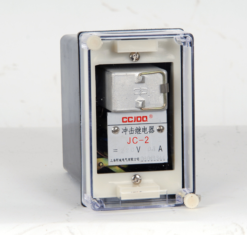
JC-2 type impulse relay is used in the relay protection and the control loop of the DC operation as the component of the centralized signal..
2, structure and working principle
The relay adopts H, Q, JK-11K shell, its external dimension, back terminal and installation of the opening - hole are shown in Appendix 3. Back terminal wiring diagram Figure 1.
Figure 1 behind terminal wiring diagram
The basic principle of the relay is the charge discharge principle of capacitor and the polarization relay as the actuating element.. Impact current IC from the terminal 5 into, in the R1 get voltage increment IcR1, the voltage across the winding of the polarized relay to capacitor C charging, the charging current polarized relay. The polarization relay has double position characteristic. When the capacitor is charged, the charge current disappears and the polarization relay contact is kept in the action position.. Its return can through the button or contact the return current pass into the terminal 2, through the resistor R2 enable polarized relay winding through the reverse current and forced to return; can also reverse impact automatic return, namely when the sigma IC decreases suddenly IC, in R1 have reduced voltage -IcR1. The voltage the capacitor by polarized relay winding discharge. The discharge current the polarized relay returns.
The typical wiring diagram used by the relay is shown in Figure 2.
3, technical requirements
1 DC rated voltage: 220V, 110V, 48V, 24V.
2 the impact action and the impact return current of 0.1A.
3 maximum stable current is 2A.
4 the power consumption of the maximum stable current is 4W.
5 contact breaking capacity
Sense (tau =5ms) circuit in DC, u is less than or equal to 250V, I is less than or equal to 1a, 20W; in the communication loop (COS phi = 0.4), u is less than or equal to 250V, I is less than or equal to 1a, 100VA.
6 insulation resistance is not less than 300M.
7 medium strength 2kV/50Hz/1min.
All circuits of the shell should be able to withstand AC 2KV (RMS), 50Hz test voltage which lasted 1min test without insulation breakdown and flashover phenomenon.
5 electrical life 8 x 10³ times.
9 weight of about 1kg.

Figure 2 JC-2 typical application wiring diagram
4, debug method
1 when the relay is connected with the power supply, the terminal 4 and 6 should be connected. With a negative voltage is applied to the terminal 2 to return.
2 when the relay connected to the negative terminal of the supply, terminals 6 and 8 should be connected, with positive voltage applied to the terminal 2 to return.
3 in order to reduce the relay fever, the resistance R1 can be modified to the external attached resistor (R1 is 1) near the relay..
. when the relay is connected to the power supply, coupled with the impact of current, relay should be check the power connection is correct, or a resistor R1 and a capacitor C is normal.
5, ordering information
Please specify the product type, name, rated data and installation method when ordering..